Real Time Maritime Lifeboat System and UML
UML example – real time system. Use Cases, Sequence Diagrams, Class Packages and Architecture example. UML is necessary to properly elicit Business and IT requirements and system constraints and objectives, including, functional and non-functional requirements.
Use Case: Maritime Lifeboat system to send out lifeboats to rescue vessels who are struggling at sea just off the coast. The system has a Maritime Controller Admin (MCA); Lifeboat Operations Management (LOM) officer; and a Lifeboat Crew. A distress signal arrives at the MCA office who must route it to the LOM and the LOM passes it on to the Crew. The objective is to launch a boat within 3 minutes of a distress event being received by the MCA. Budgets are limited given that this is a public service, funded by the government but not budget rich.
They need a newer system to replace an analogue, phone to phone system. What would you do?
Maritime Lifeboat rescue system
There are 3 critical elements when dealing with public-facing event and monitoring systems.
#1-This is a real time, event driven system.
Challenging SLAs exist, with 3 minutes from incident dispatch to launching a boat. The diagrams do not demonstrate how near-to-real time events will be sent, managed, reported on, or stored.
#2-Network availability (land, sea), must have a high availability/fail-over design.
Design offered is a ‘traditional’ approach to event architectures with limitations including a single model to fulfil event messaging, transactions, and reporting. High availability (99.99%) and key interfaces (pagers, SMS, web apps), are missing.
#3 Costs are also missing.
Given that AOL is not a for profit group, the cheapest solution is a real-time cloud-based system (pay for usage), can be built for £30.000-60.000 plus usage fees and 15% p.a. maintenance and associated network fees per annum. It is unclear where the funding would come from (a system design constraint that needs further assessment).
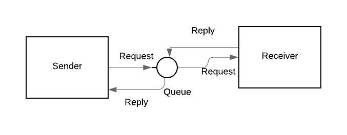
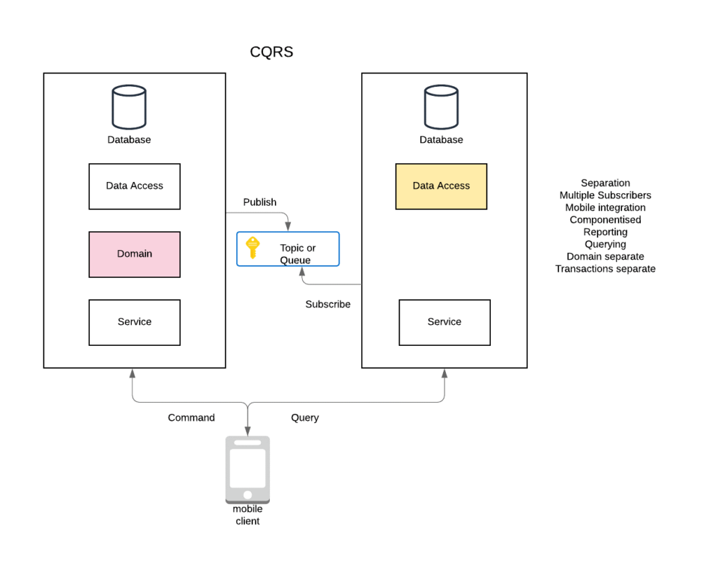
A common event architecture pattern is CQRS (command and query responsibility segregation) used in real time event systems often employing cloud technology with queues and messaging middleware. These components guarantee delivery and allow for granular event logging and reporting.
Figure: CQRS pattern
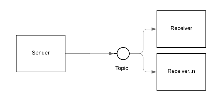
An event can trigger a command and publish an event into a channel:
- All changes are state driven and represented by events
- Reporting is updated when there is an event change
- All queries go to the reporting DB module
- SQL agent jobs can broadcast messages to a distribution group using analogue pager interfaces as well as HTTPS, SMS and Mobile protocols
- Domain or transaction model is for event transactions only
- There is a guaranteed delivery and rollback if a failure
- Subscribers can be added for high availability, backend can auto-scale
Figure: Event Architecture
This leads to a proper architecture including networking failover. A satellite link could be used to mitigate 4G network issues for boats at sea. (note: Satellite linking is complicated and involves specific hardware and extra costs: a modem, a dish, converted band signals with the dish and a 4G or Wi-Fi network).
Figure Architecture and Networking:
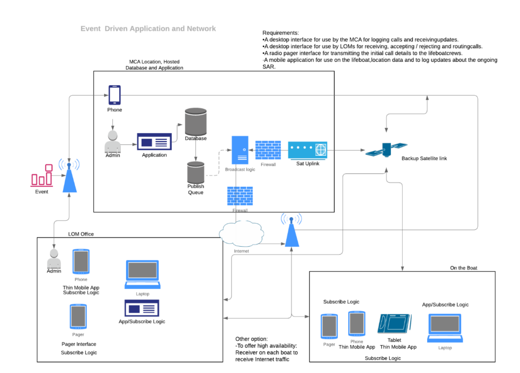
- Trigger is the live MCA operator who is notified
- Application is web and mobile based, used by all end -users integrated with a multi-channel broadcast of messages to mobile/page devices over appropriate protocols and any operating system, browser
- Voice, SMS, pager, Application and networking integration, publish (top box), subscribe (bottom boxes), including Satellite link
- All numbers are stored, edited in SQL DB
- Direct phone to phone communications is now a manual backup
- An IVR would not fulfil real time SLAs (press 1 for…2 for…3 for…)
You need to show how messages can be sent down the events-chain without human intervention. An example would be the MCA to LOM who reject the incident; this should be passed on automatically to the next closest LOM without manual intervention. An example is given below. Other detailed diagrams (E-R, Schemas) are not added for brevity.
Figure Process Flow
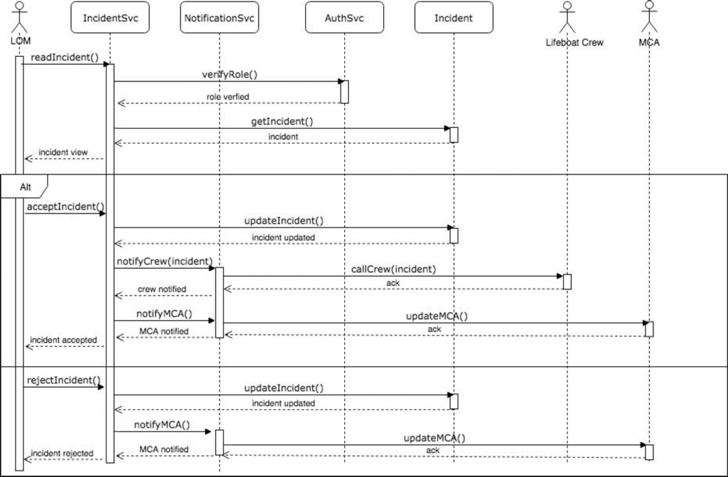
Figure: Process Flow Class Packages
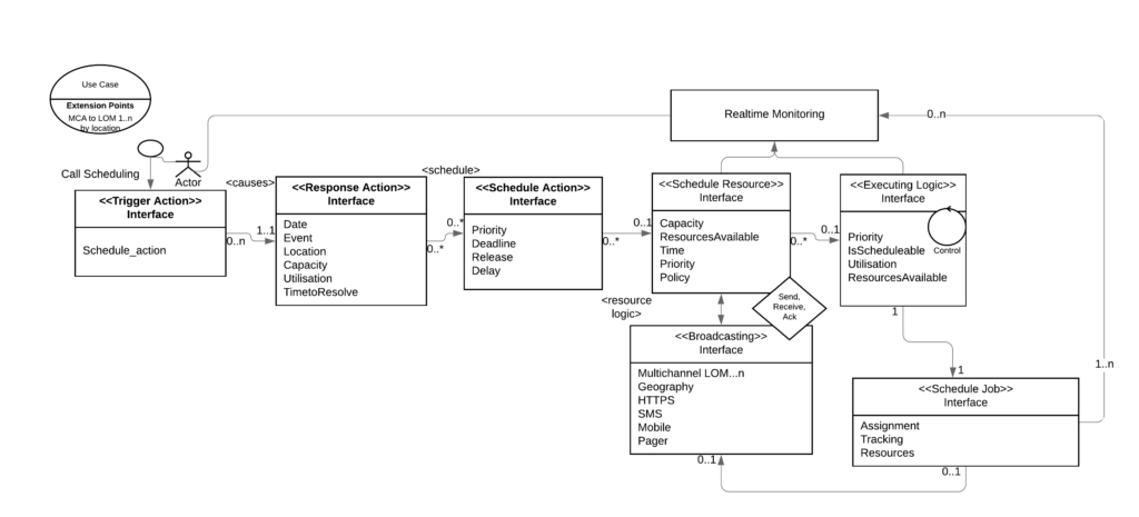
- MCA triggers the event which passes through a schema built to broadcast across protocols and route to as many LOMs as necessary to fulfil the request
- Monitoring and logging are done in real time
- Events are synchronised through a protocol, optimised for low-bandwidth constraints and supportive of wireless and terrestrial channels.
- Timestamp on events
==END