Security deployment from a real-world AWS architecture.
Cloud Security is a concern and opportunity. AWS Cloud Platform provides a best of breed security infrastructure which more secure from external attack and corruption than corporate data centres and co-location data farms. AWS has been audited and certified by many dozens of security agencies and governmental agencies. Policies, logging and monitoring are built in to AWS cloud platform solutions to provide a dashboard and overview of the environment and any threats to data and applications. Key parts of the CLIENT APP security model are covered in this document including:
- Network
- Anti-Malware/Virus
- Perimeter
- Application Attack
- Disaster Recovery
- High Availability
- Backup
Key principles: Zero Trust, Zero Touch, Encrypt everything.
Section 1: Network security
1.1 Port filters
- Only specific IP ports are allowed for external access from the Global Network.
- These are SSH(22), HTTPS(443), HTTP(80).
- SSH is secure encrypted protocol that is used only for system administrators access.
- HTTPS is secure encrypted protocol that is used for user application communication.
- HTTP is not secure, not encrypted protocol that is immediately switched to HTTPS as soon as user’s browser tries to reach HTTP. HTTP is open only for user convenience.
- FTP(20,21,47304) is open only for access from Client IP 216.88.162.55.
- All other ports are closed, including ICMP (ping, traceroute).
There are two levels of port filtering:
- AWS network policies
- System Firewall
1.2 Application Server certificate and traffic encryption
- Domain name yyy.com is secured by certificate registered at a trusted certificate authority.
- All browsers have certificate verification capabilities. The site with the correct certificate will have “Green Lock” icon near the URL, which indicates the site is verified and trusted.
- All user’s traffic goes via HTTPS only and is encrypted.
- Browsers use HTTPS. When users try to enter via HTTP, they are automatically switched to HTTPS by the SFA web application.
- The CLIENT APP application uses HTTPS and certificate verification as well.
- It is safe to access web applications from public networks.
1.3 User application access
- The CLIENT APP Sales Tool is a distributed application that consists of the following client components:
- CLIENT APP Sales Tool Client,
- Web Browser CLIENT APP Client,
- Web Browser Admin and Manager Portals.
- In each component, users are authenticated by usernames and passwords. It is important for users to use strong passwords. There is need to always implement password complexity policy in client apps.
- Each component communicates with servers via HTTPS.
1.4 CLIENT APP Sales Tool Client and Sync Process
CLIENT APP is a Java Swing based application. The data is synchronized with the back-end enterprise database using the SOAP based, sync service via HTTPS. Username and password is added to the initial SOAP request. The credentials are verified against server database and, if authenticated, a sync session is created. On each consecutive sync request, server logic checks if sync session is open and valid.
1.5 Web browser CLIENT APP
It is Angular JS based application accessed via browsers. The application communicates with the back-end enterprise database using REST services via HTTPS.
JWT token authentication is used for authenticating REST requests and guarding Angular client pages.
JWT token is generated on the server side upon successful login and passed to the client where it is saved in the HTML5 web storage. After successful login, the token is passed to the server in the header of each REST request. On the server side, each REST request goes through “JWT filter” which verifies if request contains valid JWT token.
Additionally, for securing client pages, Angular JS authentication guard is used. It allows access to the pages only if JWT token is available in the local, HTML5 web storage.
1.6 Web browser admin and manager portals
Portal application is based on Apache Wicket framework. Users are authenticated and authorized by usernames and passwords via Apache Wicket authentication provider.
1.7 FTP application access
Client synchronises required data from AS400 database to SFA database via files transfers.
There are some limitations of AS400 to use contemporary encrypted protocols (like SSH).
Files are transferred via FTP protocol, which is not encrypted (there is secure FTP but Client does FTP does not support this).
To mitigate this vulnerability, access to FTP is allowed only from Client IP aaa.bb.ccc.dd. This is set by AWS IP filter policy and the system firewall.
1.8 System administration access
System administrators can access instances or services via SSH using RSA keys and strong passwords.
Section 2.0 Attack detection and prevention
2.1 System attack detection
Special system software monitors unsuccessful attempts to login to SSH protocol and blocks an attacker IP for couple of hours after several unsuccessful attempts.
2.2 Application attack detection
Special system software monitors unsuccessful attempts to login to SFA application and blocks an attacker IP for couple of hours after several unsuccessful attempts.
Client IP will be never blocked because that would cause blocking of all other users working from office.
2.3 Rootkit/virus detection
Special system software monitors possible rootkits/virus installations and alerts system administrators if this is detected.
Section 3.0 Disaster Recovery and backup
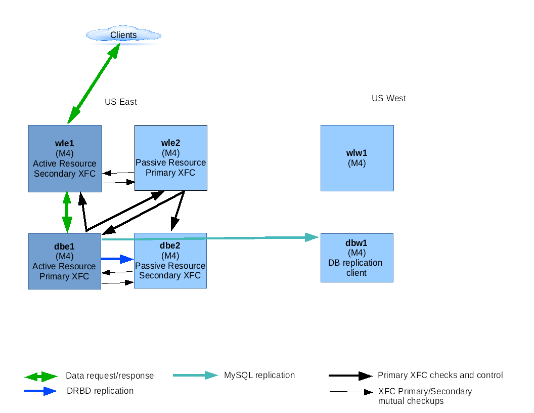
3.1 AWS architecture with HA and DR
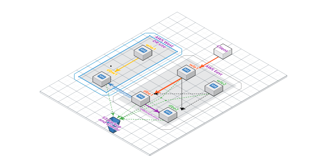
Fig. – AWS Infrastructure
Disaster Recovery (DR) is based on two HA clusters, one “US East” another “US West”, one is active another is passive.
Each HA cluster comprises of two layers, Frontend (WL), Backend (DB), within which one node is Active and another is Passive.
XFC has Control Cluster and Resource Cluster.
XFC Control Cluster where XFC services run that check and control resources that run on Resource Cluster. Resource Cluster where actual system and application resources run. It can be database, filesystem, virtual IP, etc.
WL and DB check each other. WL is Control Cluster for DB, and simultaneously DB is Control Cluster for WL.
In XFC Control Cluster one of nodes (i.e. wle1 or wle2) is Primary Node and does actual checking and managing of resources of Resource Cluster (i.e. dbe1 and dbe2). A Secondary XFC node checks if Primary Node is active. Secondary Node takes control if it detects that the Primary Node does not checking cluster.
Primary XFC Control Node checks active and passive nodes of Resource Cluster and switches its nodes roles (fails over) if an Active Resource Node has unfixable issues.
Active node in WL Resource cluster (wle1 on the diagram) is open for browsers and Sync Clients, accepts data requests and returns responses via ELB. Also, it runs FTP that is available only to Client FTP client.
Active WL node communicates with MySQL at Active DB node.
Active DB node (dbe1) replicates data changes of data filesystem(s) on block device level (DRBD) to Passive DB node (dbe2).
Active DB node (dbe1) replicates data changes of MySQL database to Active DB node at Passive HA Cluster (DBWa).
At Passive HA Cluster, in its turn, Active DB node (DBWa) replicates data changes of data filesystem(s) on block device level (DRBD) to Passive DB node (DBWb).
To avoid brain splitting and other issues Disaster Recovery switching of HA clusters done manually in case of complete disaster at Active HA cluster.
3.2 Disaster recovery procedure
There are WL and DB instances in AWS West behind an auto-scaler which can scale out to M4 large. The VMs are pre-configured in US West.
If US East region is unavailable the instances in US West will be instantiated and AMIs deployed to the Web and DB instances.
There are Elastic IP addresses which are registered in the current DNS. Elastic IPs are specific to a zone.
In case of disaster we will have different IPs in the DR West zone. DNS records will be updated with these new IPs. After that users will transparently go to DR region with no user impact.
3.3 AWS backup
Each node is backed up by taking AWS snapshots, and by Linux backup scripts to AWS cold storage.
Note:
- AWS Snapshots are AMI images that are taken periodically after significant changes.
- Backup is taken on nightly basis
- Cloudberry agent backups the AWS data backup into Azure Storage.
- EBS data volumes are encrypted.
- Data at rest is AES 256 encrypted.
Section 4.0 Code and backup
4.1 Code maintenance
Code is stored in SVN revision control system. SVN is on AWS instance. Code is committed into SVN on regular / daily bases.
4.2 Code backup
Code backup is part of AWS instances backup. Each instance is backed up by taking AWS snapshots, and by Linux backup scripts to AWS cold storage. It is backed up nightly.
Section 5.0 System monitoring and notifications
5.1 Nagios
- Nagios is configured to monitor health of server environment (i.e. check if services are up and running, disk space, memory etc.).
- Notification emails are sent in case of problems.
5.2 Log4j run-time application monitoring
- The utility monitors application health.
- Run-time server exceptions are sent via email and stored in log files.
5.3 AWS monitoring utilities
- AWS CloudWatch (hypervisor, server resource), is used to provide alerts over certain thresholds,
- AWS CloudTrail (API access and logs), is configured to provide alerts over certain thresholds,
- There is a single admin dashboard with a detailed overview of the platform’s cloud state.
==END