Provisioning overview (source)
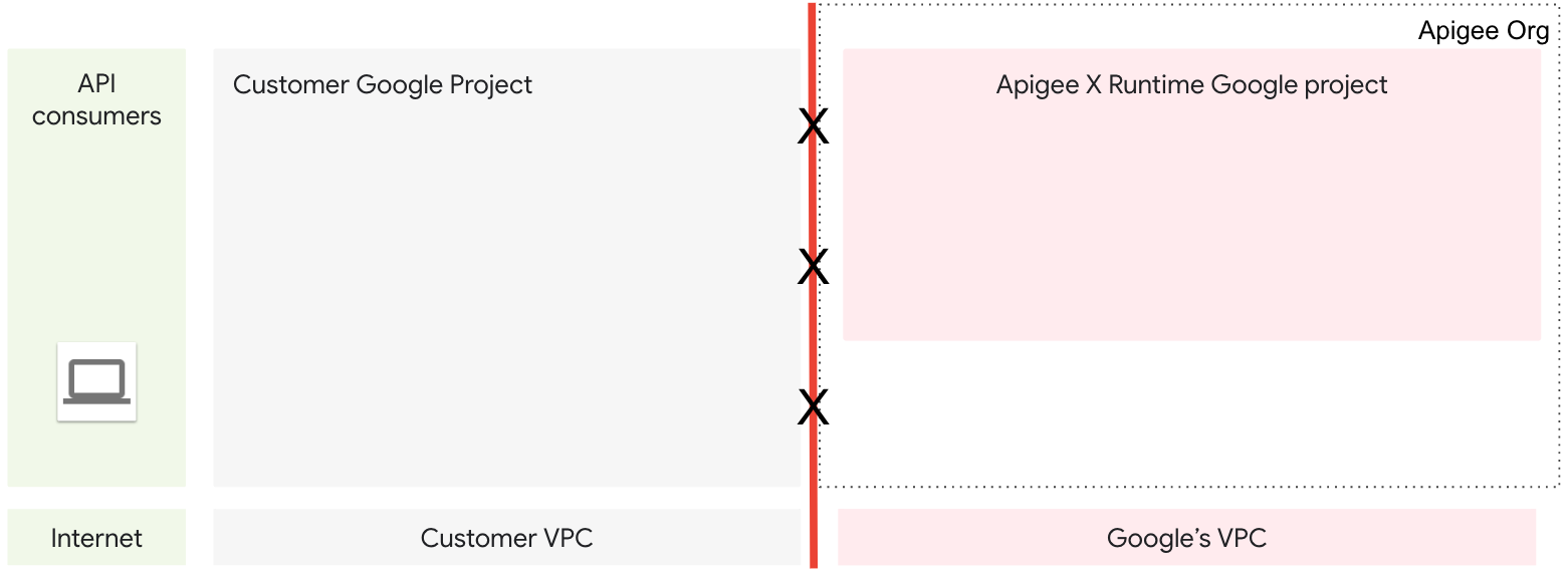
During provisioning, components are configured and created that allow bidirectional communication between a virtual private cloud network (VPC) managed by you and a VPC network managed by Apigee. After you complete the first few provisioning steps, the two VPCs exist, but as yet cannot communicate back and forth. Further configuration is needed to allow bidirectional communication. See Figure 1.
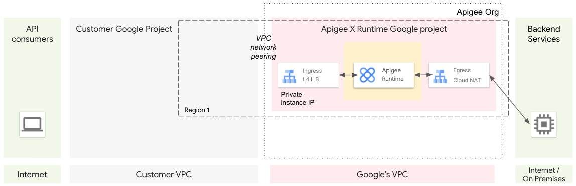
To enable communication between VPCs, we use VPC network peering. Network peering allows internal IP address connectivity across two Virtual Private Cloud (VPC) networks regardless of whether they belong to the same project or the same Google Cloud organization. After the network peering step is completed, communication is possible between the two VPCs. See Figure 2.
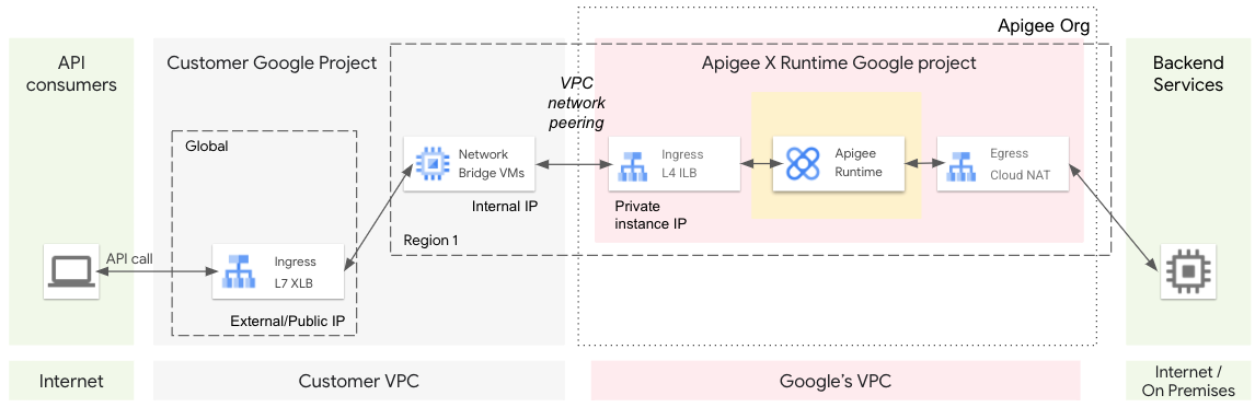
To route traffic from client apps on the internet to Apigee, we use a global external HTTPS load balancer (XLB). An XLB can communicate across GCP projects, such as between the customer GCP project and the Apigee GCP Project, using cross-project service referencing.
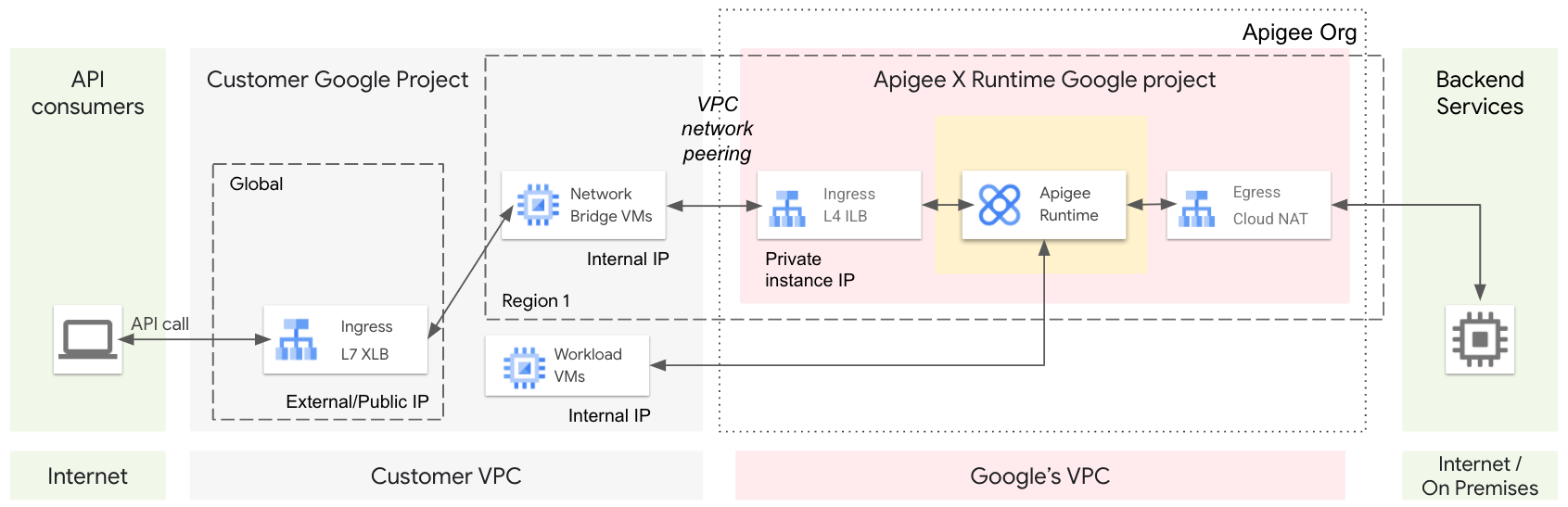
You could also provision a managed instance group (MIG) of virtual machines (VM) that serve as a network bridge. The MIG VMs have the capability to communicate bidirectionally across the peered networks. When provisioning is complete, apps on the internet talk to the XLB, the XLB talks to the bridge VM, and the bridge VM talks to the Apigee network. See Figure 3 and Figure 4.
In this configuration, traffic is routed from Apigee (for example, from the MessageLogging policy) to a workload running in your internal VPC. In this case, communication to your internal VPC does not go through a NAT IP of the Egress. Instead, you can route the traffic through one of the Apigee instance IPs.
API proxy call lifecycle
The following illustration shows the lifecycle of an API proxy call as it moves through the provisioned Apigee system components:
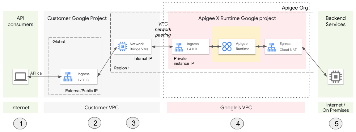
- A client app calls an Apigee API proxy.
- The request lands on a global L7 external HTTPS load balancer (XLB). The XLB is configured with an external/public IP and a TLS certificate.
- The XLB sends the request to a virtual machine (VM). The VM serves as a bridge between your VPC and Google’s VPC (managed by Apigee).Note: The XLB is not capable of communicating across the peered networks. A VM, on the other hand, can be configured to talk to Apigee across the peered network. That is why we provision a managed instance group (MIG) of VMs to function as a network bridge.
- The VM sends the request to Apigee, which processes the API proxy request.
- Apigee sends the request to the backend service, and the response is sent back to the client.
Summary
This topic presents an overview of the components that are created when you provision Apigee and describes the role of each component in the system. When you go through the Apigee provisioning process, you will see where each of the components mentioned in this overview are configured and created. Depending on your use case, you can also provision NAT IPs as a separate configuration. If you use the provisioning wizard UI, most of the work is done for you. If you use the command-line interface steps, you will see in detail the exact gcloud commands used to create each component.