Cloud Native Development Patterns and Best Practices: Practical architectural patterns for building modern, distributed cloud-native systems. by John Gilbert 2018. Available on Amazon.
An excellent book by John Gilbert on deploying Cloud Native solutions. We want to achieve global scale by recognizing that the cloud is the database, applying Reactive principles, and turning the database inside out to create proper bulkheads through the replication of data to materialized views built on event streaming, Polyglot Persistence, and cloud-native databases.
Key ideas are below.
Cloud Native some key design concepts
According to Gilbert, Cloud-native embodies the following concepts:
- A disposable virtual infrastructure;
- Composed of bounded, isolated components;
- Turns the database inside out;
- Uses sharding, polyglot storage per component;
- Scales Globally;
- Leverages value-added cloud services;
- Empowers self-sufficient, full-stack teams;
- Drives cultural change.
Cloud Native Patterns
Each pattern describes a solution to a specific problem in the context of cloud-native systems and addresses various forces, issues, and trade-offs. The patterns are interrelated and thus can be pieced together to build systems composed of bounded isolated components. There are many ways to document patterns. There are many cloud native patterns available, either as independent patterns, or as platform specific eg. AWS.
The patterns are grouped into three categories: Foundation, Boundary, and Control, to emphasize their relationships to each other and their place in cloud-native systems in general. Cloud-native patterns are documented in the following form: Name, a brief description of its intent, and a diagram that represents a sketch of the solution.
These three pieces are critical to forming a pattern language that teams can use to facilitate architecture and design discussions and to train new team members. When additional details are needed we can refer to the body of each pattern.
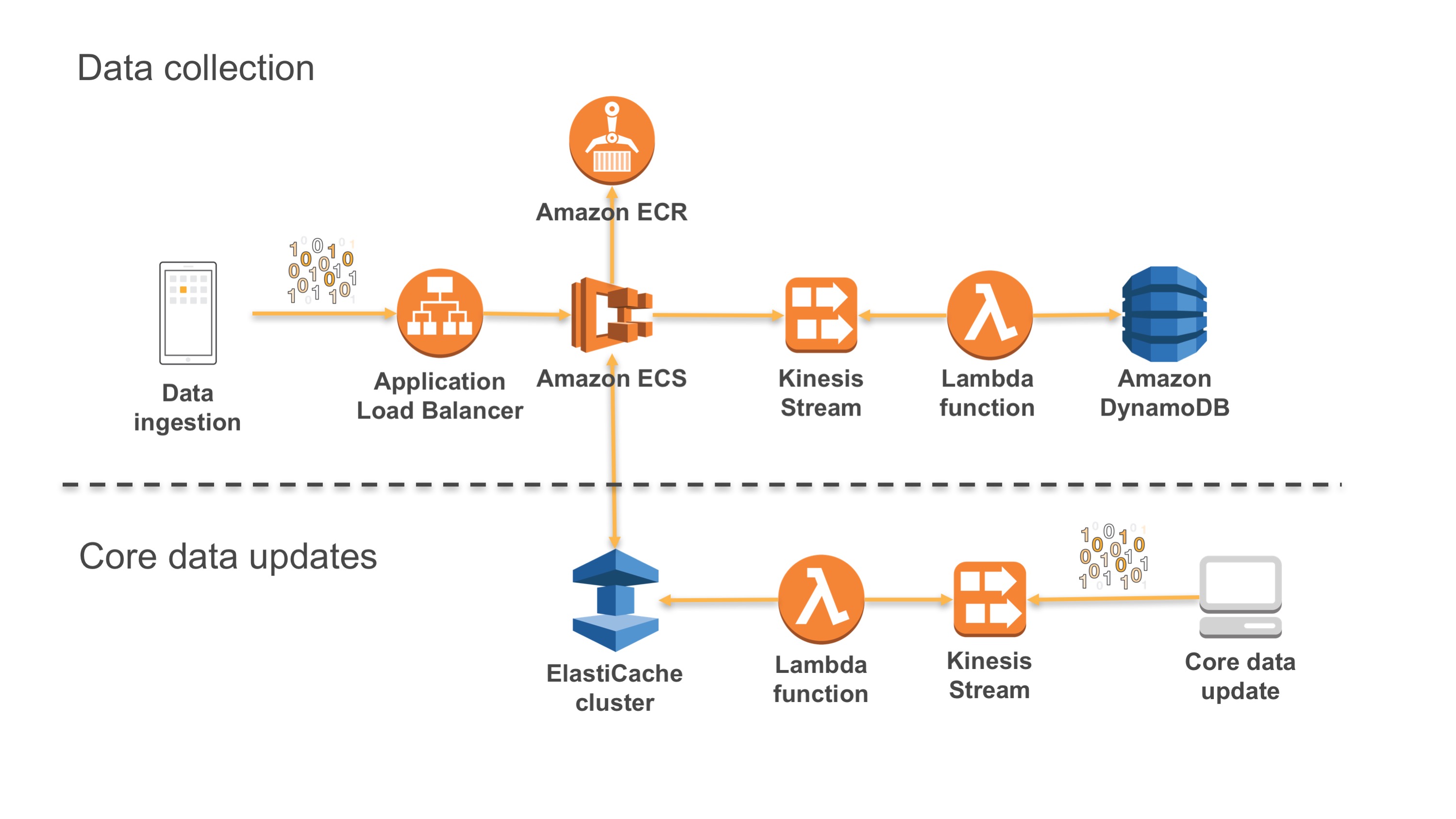
Figure: CI/CD disposable architecture
Disposable virtual infrastructure
Disposable infrastructure is also termed ‘Immutable infrastructure’. This is when we build a virtual cloud native system where our virtual instances or servers are ‘disposable’ and in which, the production environment is automated to be immutable, or immune to manual intervention including patches. If a system or one of its components fail, you dispose of that component, and rebuild or re-instantiate the application and related code. You do not need to change the instance. This ensures that the infrastructure does not deviate from its known ‘good state’. Operations are simplified (through Ci/CD automation); and failure becomes a routine fix and does not impact the business.
Component Architectures
Each component is known, isolated with boundaries and performs a specific service. Cloud Native is not monolithic. Monolithic applications are decomposed into discrete service functions at all levels of the Application stack. This allows us to build disposable architectures as well and minimise system outage and system wide risks.
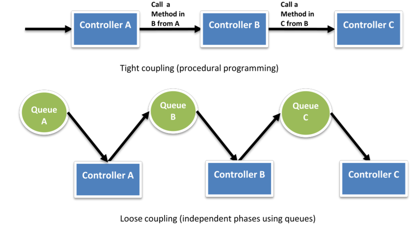
Figure: Loose coupling streams
Bounded Design
Bounded contexts are a core concept in Domain Driven Design (DDD). Domain Driven Design embraces the fact that there is no single unified model. Large models are decomposed into multiple bounded contexts with well-defined interrelationships. Each bounded context is internally consistent, such that no terms have multiple meanings. When concepts do overlap between bounded contexts, these relationships can be depicted with a context map. Domain events are used to communicate between the different contexts. What emerges is a ubiquitous language that facilitates communication between developers and domain experts.
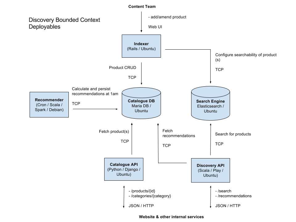
Figure: Example bounded component workflow
Data Life Cycles
Another useful strategy for decomposing a system into components is based on the life cycle of the data in the system. This is similar in concept to dividing the system based on the value streams or business processes of the system, but stretches out over a longer period. An example: how long must data be retained before it can be deleted? Data may have to live long after a business process or value stream is complete. A case in a case management system is created, assigned, and ultimately completed, but the records of the case will need to be retained and managed for an extended period.
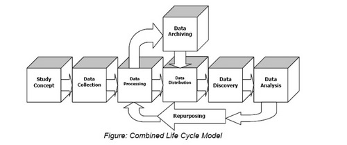
Figure: Carlton College data LCM flow
Reactive Architecture
The main principles of Reactive architecture: asynchronous, message-driven, inter-component communication to build resilient components that are responsive and elastic. Event streaming is the mechanism for inter-component communication. Components publish domain events to notify the system of their state changes. Other components consume these events to trigger their behavior and cache pertinent information in materialized views.

Figure: Reactive AWS architecture
Event Driven
Event Driven Architecture (EDA) is a design pattern in which a software component executes in response to the reception of one or more event notifications. EDA is central part of a loosely coupled, message-queue architecture. EDA is more loosely coupled than the client/server paradigm because the component that sends the notification doesn’t know the identity of the receiving components at the time of compiling.
The classic example of event-driven, non-blocking, eventual consistency is the coffee shop. You stand in line at the coffee shop and wait for your turn to place and pay for your order. Then you wait for your cup of coffee to be prepared. If all goes to plan then your order is ready promptly. Otherwise, you inquire about your order when it is taking too long.
Streaming
Streaming is basically the ability to change the system quickly in response to changing needs. The main principle is decoupling between data sources or providers and consumers, via data queues and batch streams. Stream processors leverage batches in combination with functional reactive programming and asynchronous non-blocking IO to create robust, elegant, and highly concurrent processing logic. Stream processors are replicated per shard to further increase concurrency.
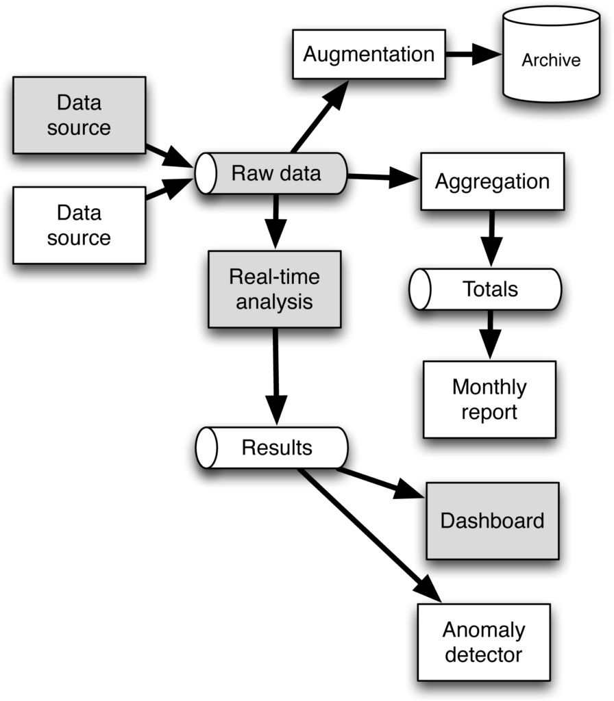
Figure: Event driven, streaming architecture
Eventual Consistency
S3 from AWS is an example of eventual consistency. This means that edits and deletes on objects are eventually consistent or rendered, across multi-region DCs. It is widely preferred to design systems around eventual consistency and session consistency. Event streaming and eventual consistency are interdependent. Eventual consistency is simply a reality of asynchronous messaging and event streaming is the mechanism for implementing eventual consistency.
With eventual consistency we can increase responsiveness and scalability by allowing components to delegate processing to downstream components. More importantly, we can build bounded isolated components that are resilient and elastic, because event streaming and eventual consistency are crucial to turning the database inside out (to use Gilbert’s own words).
Polyglot Persistence
Polyglot Persistence is an approach where the system is composed of many different types of databases. Each component in the system uses the right storage technology for the job and often multiple kinds of databases per component. Some of the different categories of databases include key-value stores, document stores, search engines, graph databases, time series databases, blob or object storage, mobile offline-first databases, columnar or column-oriented data warehouses, and append-only streams.
On a component-by-component basis, the idea is that we should choose to use the storage mechanism that best suits the requirements of the specific component. One unique characteristic of polyglot persistence is that we will often use multiple storage mechanisms within a single component to get the absolute best performance and scalability for the specific workload. Optimal persistence is crucial for global scale, cloud-native systems.
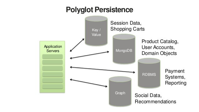
Figure: Polyglot Persistence
Sharding
Traditional databases are unable to scale to meet the demands of global cloud applications because they were designed to scale vertically. Modern databases have been designed to leverage sharding, which allows them to scale horizontally by partitioning the data across multiple nodes. This improves responsiveness because it reduces contention for disk access; it provides resilience because the data is also stored redundantly across several machines; and allows the database to be elastic, as the demand grows, by adding partitions. Yet, sharding is not sufficient in and of itself. Many specialized databases have been built on top of sharding that are optimized for very specific workloads.
The above means that one table can be a document store, another table is a search index, and another table is blob storage.
Many of these cloud-native databases are actually designed to support this inside-out database architecture and expose their transaction logs as an event stream, to facilitate the Event Sourcing and CQRS patterns.

Figure: Oracle Sharding
The Cloud as a Database
Traditional databases maintain materialized views. A materialized view is yet another copy of the data, which is the result of a query that is continuously kept up to date by the database. These are examples of derived data, that, other than the cache, are managed by a single database cluster. Databases to do a great deal of work and can be slow. An objective is to take the back-end processing and turn it inside out, so that we can spread this processing across the cloud, to achieve massive scale and sufficient isolation.
==END